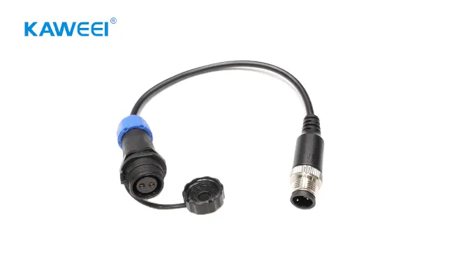
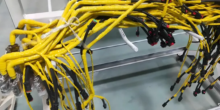
Cable voltage drop occurs when current flows through the resistance and impedance of electrical cables and custom wire harness assemblies. Excessive voltage drop lowers terminal voltage at loads, leading to unstable equipment operation, reduced efficiency, and premature component wear. For wire harness assembly design and manufacturing, voltage drop verification is a critical step to ensure finished harnesses meet real-world operating requirements.
The key variables that determine harness voltage drop include conductor length, wire cross-sectional area, load current, operating temperature, and parasitic resistance from connectors and terminals. This practical guide covers accurate voltage drop calculations, industry-recommended voltage-drop limits, root causes, and targeted optimization methods tailored specifically for wire harness applications.
1. What Is Cable Voltage Drop?
Voltage drop is the measurable electrical potential difference between the power supply end and the load end of a live circuit. All conductive wires and assembled harnesses contain inherent impedance that resists current flow.
Conductors have electrical resistance that causes voltage drop and dissipates energy as heat when current flows. In AC circuits, impedance may also include inductive or capacitive reactance, depending on the circuit configuration and operating frequency.
Minor voltage drop is unavoidable in all wiring systems. However, unregulated voltage loss can pull load voltage below equipment minimum operating thresholds. Importantly, voltage drop is a normal circuit characteristic and must not be confused with faults such as overcurrent, short circuits, or insulation failure—these issues have distinct causes and risk mechanisms.
2. Core Causes of Harness and Cable Voltage Drop
Five core factors directly determine voltage loss in standard cables and custom wire harnesses:
2.1 Conductor Length
Conductor resistance increases with wire length. Longer routing paths and unnecessary excess wire increase total circuit resistance and voltage drop. This is an important contributor to excessive voltage loss in long-distance industrial wiring, outdoor equipment, and extended automotive harnesses.
2.2 Wire Cross-Sectional Area (Wire Gauge)
Conductor resistance decreases as wire cross-sectional area increases. Thinner wires offer higher resistance and suffer more significant voltage drop under equivalent load current, while larger cross-sectional area conductors minimize resistive loss. Selecting a proper wire size is the most effective design method to control voltage drop for fixed-length harnesses.
2.3 Load Current
Voltage drop rises proportionally with load current per basic circuit principles. Concentrated high-power loads on a single harness branch increase operating current, amplifying voltage loss. Harness designers must verify voltage drop for high-current loops to prevent under-voltage operation at terminal devices.
2.4 Conductor Material and Temperature
Copper and aluminum are the primary conductor materials for electrical wiring and harnesses. Copper has relatively low electrical resistivity and stable electrical conductivity, making it ideal for precision custom harnesses. Its reliable termination performance depends on matched terminals, standardized crimping processes, and material compatibility. Aluminum has higher resistivity than copper, so a larger conductor cross-sectional area is generally required to achieve comparable resistance. Its suitability depends on application needs, weight and cost constraints, termination methods, and applicable electrical codes.
All metal conductors gain resistance as temperature rises. Continuous load operation and high ambient temperatures increase wire resistance, further exacerbating voltage drop in active harness systems.
2.5 AC and DC Circuit Differences
In steady-state DC circuits, voltage drop is primarily determined by the resistance of the conductors and other series components in the current path, including connectors and terminals. In AC circuits, resistance and inductive reactance may also affect voltage drop, depending on circuit configuration, frequency, and load power factor.
For this reason, AC voltage drop calculations require additional parameters beyond current, length, and resistance. There is no universal rule that AC voltage drop is consistently higher than DC; results depend entirely on circuit-specific electrical characteristics.
3. Acceptable Voltage Drop Limits (Industry Standards)
Allowable voltage drop values are not universal mandatory figures. They vary by regional electrical codes, project specifications, and OEM equipment requirements.
In the United States, informational notes associated with the NEC commonly recommend limiting voltage drop to 3% for branch circuits and 5% for the combined feeder and branch-circuit path. These are design recommendations, not universal mandatory limits for every wiring application. Wire harness acceptance criteria should be based on the applicable standards, project specifications, and the load's minimum operating voltage.
All harness design and validation must reference applicable local codes and project specifications to confirm compliant voltage drop thresholds.
4. Standard Voltage Drop Calculation Formulas
Industry-standard formulas below include clear unit rules and application limits to avoid engineering calculation errors during wire gauge selection and harness optimization.
4.1 DC Circuit Formula
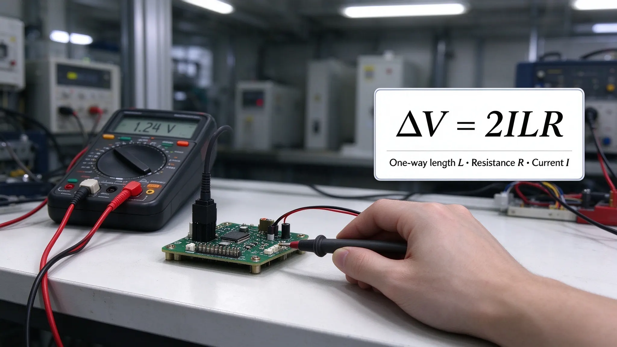
DC Voltage Drop = 2 × I × L × R
Parameters & Application Rules:
DC Voltage Drop: Total circuit voltage drop (V); I: Load current (A); L: One-way harness length (m); R: Single conductor unit-length resistance (Ω/m).
This formula applies to symmetrical two-wire DC circuits with identical positive and negative conductors. For asymmetrical circuits with different wire gauges or lengths on each leg, calculate voltage drop for each conductor separately and sum the total loss. All units must remain consistent to avoid magnitude errors.
4.2 Single-Phase AC Formula
The following approximate formula is commonly used to estimate voltage drop in a single-phase AC circuit:
AC Single-Phase Voltage Drop = 2 × I × L × (R × cosθ + X × sinθ)
These formulas provide approximate voltage-drop estimates for circuits with the stated configurations. They assume equal-length outgoing and return conductors for single-phase circuits and balanced operation for three-phase circuits. The sign and magnitude of the reactance term depend on the load power factor and circuit conditions. For leading power factors, unbalanced loads, or complex circuit configurations, a more detailed calculation may be required.
4.3 Three-Phase AC Formula
AC Three-Phase Voltage Drop = √3 × I × L × (R × cosθ + X × sinθ)
Use conductor resistance values appropriate for the expected operating temperature when estimating voltage drop. Separately, verify ampacity under the applicable ambient-temperature, bundling, and installation conditions. Complex or unbalanced three-phase circuits may require more detailed analysis.
For quick preliminary estimates, use our [Wire Gauge Calculator] to identify suitable conductor sizes. Final selection must account for allowable voltage drop, operating temperature, installation constraints, and connector ratings.
5. Practical 12V DC Harness Calculation Example
This industry-relevant case simulates a typical low-voltage wire harness application for automotive, battery-powered, and industrial device systems:
Case Conditions: 12V DC harness, 5A load current, 5m one-way length, 0.01Ω/m single-conductor resistance, symmetrical positive/negative wiring.
Calculation Results:
1. Total voltage drop = 2 × 5 × 5 × 0.01 = 0.5V
2. Voltage drop percentage = (0.5 / 12) × 100% = 4.17%
3. Load terminal voltage = 12 - 0.5 = 11.5V
Engineering Note: The calculated voltage drop is 4.17%, leaving 11.5 V at the load under the stated assumptions. The 0.01 Ω/m unit resistance used in this case is a simplified example parameter for demonstration purposes. Actual conductor resistance varies with wire gauge, material, and operating temperature. Whether this voltage drop value is acceptable depends on the equipment's minimum operating voltage and the applicable project requirements. For a 12 V harness, designers should verify the voltage available at the load under worst-case operating conditions, including conductor heating, connector resistance, and peak current demand.
6. Practical Impacts of Excessive Voltage Drop
Excessive voltage drop creates measurable operational issues for wired systems, with clear distinctions from overcurrent and thermal failure modes:
6.1 Degraded Equipment Performance
In 12 V and 24 V harness systems, a given absolute voltage drop represents a larger percentage of the supply voltage than it does in higher-voltage systems. Its effect on equipment operation depends on the load's minimum input-voltage requirement and operating conditions.
6.2 Accelerated Component Aging
Some regulated or constant-power loads draw more current as input voltage falls in an attempt to maintain their power output. Motors may also experience reduced torque, slower operation, or stalling when terminal voltage is insufficient. The resulting current and thermal effects depend on the load type and operating conditions, rather than applying universally to all inductive devices.
6.3 Indirect Electrical Safety Risks
Excessive voltage drop is not, by itself, proof of an overcurrent condition or an imminent fire hazard. However, resistive voltage drop is associated with power dissipation in the current path. High current, excessive resistance, poor connections, or unsuitable conductor sizing can produce localized heating and increase safety risks. Voltage drop, conductor temperature, and circuit protection should therefore be evaluated separately but together.
6.4 Reduced System Energy Efficiency
Resistive voltage loss converts usable electrical energy into waste heat. Unoptimized harness designs with chronic excessive voltage drop increase operational power consumption and reduce overall system efficiency.
7. Effective Voltage Drop Reduction Methods for Harnesses
7.1 Select Optimized Conductor Material and Wire Gauge
Match conductor material and cross-sectional area to load current, harness length, allowable voltage drop, and operating temperature. Copper is widely used in wire harnesses because of its relatively low electrical resistivity. Termination reliability depends on compatible terminals, suitable crimp design, and controlled assembly processes. For long or high-current harness runs, upsizing wire gauge reduces circuit resistance and suppresses voltage drop. Final selection must validate ampacity, insulation temperature ratings, and connector specifications.
7.2 Optimize Harness Routing to Minimize Length
Eliminate redundant wiring, unnecessary looping, and excessive coiling in harness layouts. Shortening current paths reduces total conductor resistance, providing a cost-effective method to control voltage drop at the design stage.
7.3 Balance Circuit Load Distribution
Avoid overloading single harness branches with multiple high-power devices. Distribute heavy loads across independent circuits to reduce individual loop current. For AC systems with notable reactive power characteristics, evaluate power factor conditions and system-level compensation only where applicable, rather than applying generic compensation solutions to individual harness loops.
7.4 Control Operating Temperature and Harness Integrity
Use conductors and insulation rated for the expected operating temperature. Account for ambient temperature, harness bundling, and installation conditions when checking ampacity and conductor temperature rise. Avoid mechanical damage, excessive compression, and poor terminations, which may increase local resistance and cause overheating. Proper crimping and standardized assembly help control contact resistance and stabilize long-term electrical performance.
8. Voltage Drop Considerations for Custom Wire Harnesses
Custom wire harnesses differ from single standalone cables, featuring multi-branch layouts, multiple series connectors, mixed wire sizes, and vibration-prone installations. These unique structures create voltage drop challenges that basic cable calculations often overlook.
Connector contact resistance acts as fixed series resistance in a current path, separate from wire conductor resistance. For a single current path in which the same current flows through all series components, the voltage drop can be estimated as: Total Voltage Drop = I × (Total Conductor Resistance + Total Contact Resistance). Here, total conductor resistance includes all wire segments along the analyzed path, while total contact resistance includes the resistance of the relevant series connectors and crimp joints. For branched harnesses with different currents in individual segments, calculate the voltage drop across each segment using its actual current, then sum the drops along the path to the load.
For multi-branch harnesses, calculate voltage drop independently for each current path, as branch lengths, wire sizes, and load currents vary. In automotive and mobile equipment harnesses, vibration may degrade connection integrity and increase contact resistance over time. Designers should reserve reasonable voltage margin by verifying load voltage under worst-case working conditions to ensure long-term stable harness performance.
9. Frequently Asked Questions (FAQ)
9.1 What Is an Acceptable Voltage Drop in a Cable or Harness?
There is no single universal voltage-drop limit for every cable and harness application. NEC informational notes provide common non-mandatory design guidelines: 3% for branch circuits and 5% for combined feeder-branch systems. Final acceptable thresholds are defined by applicable local codes, project specifications, and the load’s minimum operating voltage.
9.2 How Do You Calculate Voltage Drop in a DC Cable?
Apply the DC voltage drop formula (DC Voltage Drop = 2 × I × L × R) with fully unified units. Calculate absolute voltage loss, then derive the percentage drop to validate harness design feasibility.
9.3 Does a Longer Cable Cause More Voltage Drop?
Yes. Longer conductors increase total circuit resistance, leading to higher voltage drop under identical load and operating conditions.
9.4 Does a Larger Wire Gauge Reduce Voltage Drop?
Yes. Larger cross-sectional wire conductors have lower unit resistance, effectively minimizing resistive voltage loss for long wiring runs and high-current harness applications.
9.5 What Is the Difference Between Voltage Drop and Power Loss?
Voltage drop refers to the potential difference between two circuit points, while power loss describes the rate of thermal energy dissipation. Though distinct metrics, they are closely correlated. For resistive DC circuits, power loss can be calculated as Power Loss = I × Voltage Drop = I² × R.
9.6 How Does Voltage Drop Affect 12V Wire Harnesses?
In a 12 V wire harness, a given voltage drop represents a larger proportion of the supply voltage than it would in a higher-voltage system. Whether the drop affects operation depends on the load's input-voltage range and the minimum voltage available under operating conditions. Designers should verify the voltage at the load, especially during startup or peak-current demand. Voltage drop verification is an important design check for all low-voltage harness assemblies.
10. Conclusion
Cable voltage drop depends on conductor resistance, circuit current, cable length, operating temperature, and resistance at connection points. For custom wire harness assembly, designers should calculate voltage drop along each relevant current path and verify that the load receives sufficient voltage under expected operating conditions. Proper conductor sizing, sound terminations, and appropriate routing effectively control voltage drop and maintain consistent electrical performance for industrial, automotive, and low-voltage harness applications.