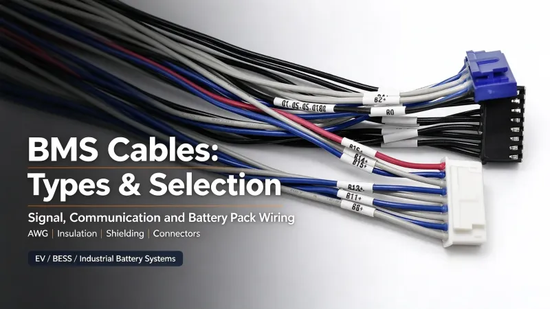
Battery Management System (BMS) cables form the physical signal and low-power link between battery cells, sensors, monitoring boards, and main controllers in lithium battery systems. Unlike high-current battery power cables, these specialized wires handle cell sampling, temperature detection, and system data communication—directly impacting monitoring accuracy and battery operational safety. Improper cable selection causes signal distortion, false system alerts, and long-term pack reliability issues. This practical guide targets design engineers and procurement teams, covering BMS cable types, structural specifications, field selection rules, and custom procurement standards for EV and energy storage projects.
1. What Is a BMS Cable?
A BMS cable refers to a wire or cable assembly dedicated to battery monitoring, temperature sensing, data communication, and auxiliary power supply in battery management systems. Its conductor size, insulation rating, and overall construction vary by circuit function and battery system architecture. Notably, low signal current does not equate to low insulation requirements; series-connected battery packs often require high insulation voltage ratings for low-current sampling lines to avoid electric potential risks.
To eliminate industry confusion, it is critical to distinguish three easily confused wiring concepts in battery systems:
1.1 Core Differences: BMS Cable vs. BMS Wiring Harness vs. Battery Power Cable
-
BMS Cable: Single wire or basic cable assembly for low-voltage signal sampling, temperature sensing, and device auxiliary power, sized for precise weak-signal transmission rather than power load.
-
BMS Wiring Harness: A finished integrated assembly formed by bundling multiple functional BMS cables, matched with terminals, connectors, insulating sleeves, and fixing accessories. It is pre-assembled for plug-and-play installation in battery packs.
-
Battery Power Cable: A high-current primary cable responsible for battery pack charge and discharge power transmission. It requires large wire gauges, high temperature resistance, and strong load capacity, and is completely different from low-voltage BMS signal cables in design and application standards.
In short, BMS cables focus on signal acquisition and data interaction, while battery power cables undertake high-current energy transmission. Mixing up their specifications leads to functional and safety risks.
1.2 Typical Connection Logic of BMS Cables
BMS signal paths vary by system topology (centralized, distributed, daisy-chain). In mainstream wired systems, individual sampling and temperature cables collect on-site battery data and transmit it to local monitoring circuits, while dedicated communication cables transfer processed data between BMS controllers, vehicle ECUs, and cloud energy storage platforms for real-time regulation and fault protection.
2. Types of BMS Cables and Wiring Harnesses
BMS cables are functionally classified based on their roles in battery monitoring and communication. No single cable type fits all scenarios; configurations are customized per battery system architecture. Below are the four core functional types and integrated harness assemblies:
2.1 Battery Monitoring and Voltage-Sensing Cables
Voltage-sensing cables connect individual cells and modules to BMS acquisition boards, collecting real-time cell voltage data to support over/undervoltage protection and cell balancing. They require low and stable contact resistance to prevent sampling errors, with thin-strand conductors optimized for compact battery pack layouts.
These cables require low and stable contact resistance to preserve measurement accuracy, as minor signal fluctuations can cause inaccurate voltage sampling and false system alarms. Thin-gauge stranded conductors are commonly used for compact battery pack installations, with final specifications determined by circuit design and mechanical constraints.
2.2 Temperature Sensor Cables
Matched with NTC/PTC thermistors, temperature sensor cables transmit real-time temperature data of battery cores and modules. They feature high weak-signal sensitivity to avoid data distortion under temperature fluctuations, supporting BMS thermal protection and charge/discharge strategy adjustment.
2.3 BMS Communication Cables
Communication cables enable bidirectional data transmission between BMS and upper-level devices. Cable selection depends on system protocol, network topology, transmission distance, data rate, and EMC environment, rather than simple application scenarios. The two mainstream interface standards are CAN bus and RS-485:
-
CAN Bus Cables: Standard twisted-pair structure with fixed impedance, supporting high-speed, fault-tolerant differential signaling. Widely used for high-reliability real-time data interaction, with shielding configured per EMC design requirements.
2.4 BMS Power and Auxiliary Cables
-
RS-485 Cables: Differential transmission design for stable long-distance communication, suitable for medium and low-bandwidth monitoring systems. Shielding and pair structures are customized based on on-site electromagnetic interference levels.
Auxiliary power cables supply stable low current for BMS controllers and acquisition boards. Core requirements focus on anti-surge performance and steady voltage output to ensure normal operation of electronic monitoring components.
2.5 Battery Pack Wiring Harnesses
BMS wiring harnesses are integrated assemblies of the above single-function cables, bundled, insulated, and assembled with customized connectors. Integrated harnesses simplify battery pack modular installation and can be fitted with fixed brackets, heat-shrink tubes, and shielding structures per customer structural designs.
4. BMS Cable Construction and Key Components
4.1 Conductor Material and Stranding Structure
BMS cable signal stability and environmental adaptability depend on four core structures: conductor material, insulation sheath, shielding design, and terminal crimping. Each component has clear engineering design boundaries:
Qualified BMS cables adopt stranded tinned copper conductors. Tin plating improves surface oxidation and corrosion resistance for stable long-term terminal crimping. Multi-strand fine wire structures enhance flexibility and anti-fatigue performance, adapting to vibration and frequent bending in vehicle and industrial battery packs.
4.2 Insulation and Sheath Materials
PVC, XLPE and TPE are widely used for wire insulation and sheaths. There is no simple one-to-one rule to match each material to an application. Material selection depends on validated product specifications: rated temperature, insulation voltage, flame resistance, abrasion resistance and chemical compatibility. For outdoor or exposed wiring, UV resistance and environmental tolerance must also be verified:
-
PVC: Cost-effective, basic mechanical performance, for indoor, low-vibration, moderate-temperature environments;
-
XLPE: Excellent high-temperature aging resistance and dielectric stability, for long-term continuous operation scenarios (outdoor applicability requires formal UV-resistant grading certification);
4.3 Connectors, Terminals and Crimping Structure
-
TPE: High flexibility and low-temperature toughness, for compact installation spaces and dynamic vibration working conditions.
Connectors and terminals determine electrical contact reliability. We adopt standardized precision crimping processes to guarantee consistent crimp quality and stable signal transmission. Compatible components include automotive-grade waterproof connectors, board-to-board terminals, and customized pin headers, with all pin configurations customized per project drawings.
4.4 Shielding and EMC Anti-Interference Design
Shielding and twisted-pair configurations are determined by circuit sensitivity, cable routing, system EMC design, and on-site noise conditions. High-speed communication lines usually require standardized twisted pairs and shielding; voltage and temperature sampling lines may also need noise suppression in high-interference industrial and vehicle environments. Shielding must be matched with standardized grounding and termination to ensure actual signal integrity.
4.5 Auxiliary Protective Structures
Auxiliary protections including heat-shrinkable tubes, wrapping tapes, and fixed brackets reduce wire friction and terminal tensile stress during equipment operation, improving overall harness structural durability.
5. BMS Cable Specifications and Design Requirements
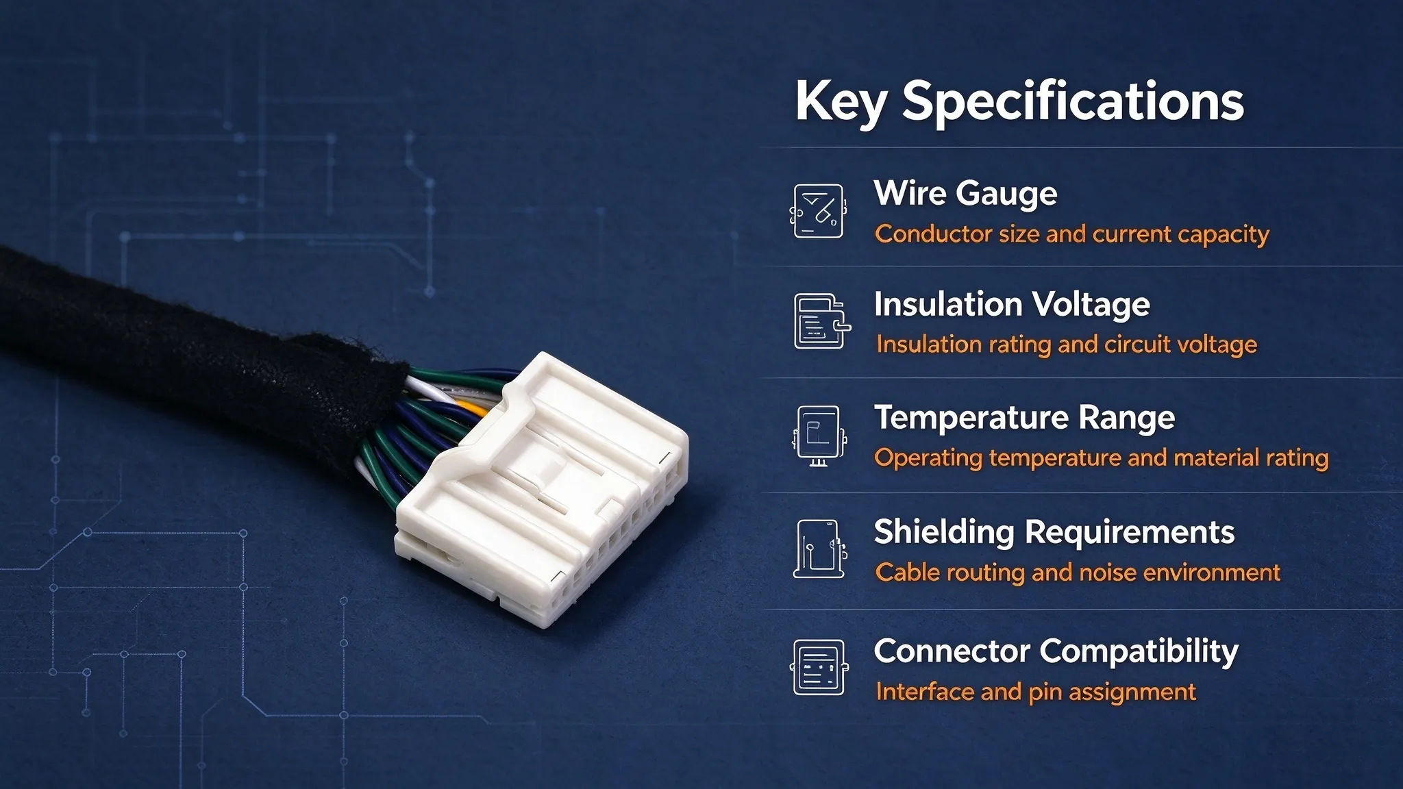
BMS cable parameter selection must follow engineering boundary conditions rather than empirical rules. The table below lists core specification verification standards and key checkpoints for project design and procurement:
|
Core Specification
|
Why It Matters
|
Key Verification Points for Procurement
|
|
Wire Gauge (AWG)
|
Improper wire gauge causes signal attenuation, excessive voltage drop, or installation incompatibility, affecting long-term circuit stability
|
Determined by circuit current, allowable voltage drop, conductor resistance, cable length, temperature derating, and mechanical constraints. Select strictly per approved system design specs, no generic AWG range applies.
|
|
Rated Voltage & Current
|
Ensures insulation safety and stable operation under normal and transient system conditions
|
Insulation voltage rating must be verified separately from working current. Low-current signal lines in series battery packs may require high insulation grades, determined by battery architecture, maximum system voltage, and transient surge conditions.
|
|
Operating Temperature Range
|
Determines material aging rate, mechanical stability, and service life in variable working environments
|
Match insulation and sheath materials to project-specific operating temperature cycling and certified material temperature grades.
|
|
Insulation & Wear Resistance
|
Prevents insulation damage, short circuits, and wire failure caused by internal extrusion and friction inside battery packs
|
Verify material test reports to ensure abrasion and extrusion resistance matches compact battery pack installation conditions.
|
|
EMC & Shielding Performance
|
Preserves signal integrity in complex electromagnetic interference environments
|
Configure twisted-pair and shielding structures based on interface standards, routing layout, and system EMC validation requirements.
|
|
Connector Compatibility
|
Guarantees seamless assembly, stable contact, and interchangeability between cables and system terminals
|
Confirm connector model, pin definition, and crimping specs to match BMS hardware and project drawings.
|
All specifications are project-specific. No universal standard covers all BMS cable applications; final confirmation against system design and operating conditions is mandatory.
6. Step-by-Step BMS Cable Selection Process
Follow this streamlined engineering workflow to avoid over-design, under-specification, and mismatched configurations:
Step 1: Confirm BMS Architecture and Signal Type
Clarify BMS system topology and cable functional type (voltage sampling, temperature sensing, CAN/RS485 communication, auxiliary power), and confirm mandatory shielding and structural requirements.
Step 2: Determine Accurate Electrical Parameters
Confirm signal type and circuit requirements first. Select wire gauge and cable structure based on working current, allowable voltage drop or measurement error, cable length, insulation rating, and installation constraints.
Step 3: Verify Connector and Terminal Matching
Verify full compatibility of connector models, pin assignments, and terminal crimping specifications with BMS hardware and battery module interfaces.
Step 4: Evaluate Environmental and Mechanical Conditions
Evaluate on-site temperature cycling, vibration, humidity, and space limitations to select matched insulation materials and protective structures.
Step 5: Confirm EMC and Anti-Interference Requirements
Configure shielding and EMC protection schemes according to system anti-interference standards and ambient noise levels, balancing performance and cost.
7. BMS Cable Applications
7.1 EV and Hybrid Vehicle Battery Systems
BMS cable performance requirements vary drastically by operating environment. Core scenario-based criteria are summarized below:
EV battery pack cables withstand continuous vibration, wide temperature cycling, moisture, and abrasion. Automotive-grade assemblies require strict environmental resistance to ensure long-term stable signal monitoring.
7.2 Battery Energy Storage Systems (BESS)
Grid-scale BESS requires 24/7 continuous operation. Cables must deliver excellent aging and humidity resistance to support long-term uninterrupted monitoring and low maintenance frequency.
7.3 Residential and Commercial Energy Storage
Residential and commercial energy storage features compact enclosed spaces, requiring flexible, low-noise, high-safety cable assemblies for long-term indoor operation.
7.4 Industrial Battery Packs and Backup Power Systems
Industrial battery packs and UPS backup systems face variable harsh environments. Cables need robust impact resistance and stable low-load performance for long standby-cycle operation.
8. BMS Cable Assembly Manufacturing and Quality Testing
8.1 DFM Review and Process Customization
Custom BMS harness reliability relies on standardized production processes and tiered, project-aligned quality control. All manufacturing and testing statements below are verifiable and consistent with actual factory quality systems:
Our engineering team conducts DFM reviews for every custom project, optimizing harness layout, wire length, and protection structures to eliminate manufacturability risks and formulate targeted production workflows.
8.2 Standardized Production Processes
We adopt automated wire cutting, precision insulation stripping, and computer-calibrated terminal crimping to ensure consistent crimp precision and dimensional stability, reducing manual operation deviations.
8.3 Project-Aligned Quality Testing & Validation
We implement tiered testing standards for full transparency: 100% inline testing covers continuity, open/short circuit detection, and insulation resistance for all finished products. Terminal retention tests are conducted via first-piece validation and batch sampling. High/low temperature cycling, vibration aging, and EMC testing are implemented per customer project certification requirements, with formal test reports provided accordingly.
8.4 Batch Traceability Management
Complete batch production records, sample validation files, and engineering change logs are retained for full lifecycle traceability. Qualified batches are delivered with matched test documents to support quality accountability.
9. Custom BMS Cable Assemblies: What to Include in an RFQ
|
RFQ Item
|
Detailed Requirements to Provide
|
|---|---|
|
Application Scenario
|
EV/hybrid vehicle, BESS, residential storage, industrial backup power; clarify key environmental working conditions
|
|
Drawings & Samples
|
Submit 2D/3D drawings, wiring diagrams, or physical samples for structural sizing and layout confirmation
|
|
Electrical Requirements
|
System voltage, signal type, rated current, and applicable industry certification standards
|
|
Wire Specifications
|
Wire gauge, conductor/insulation material, single wire length, and color coding requirements
|
|
Connector Requirements
|
Connector brand, model, pin count, pin definition, and terminal plating requirements
|
|
Environmental Conditions
|
Temperature range, vibration resistance, IP waterproof/dustproof grade, humidity, and corrosion resistance needs
|
|
Testing & Acceptance
|
Required test items, acceptance criteria, and certification/test report documents
|
|
Production Requirements
|
Sample quantity, annual mass production demand, delivery cycle, and packaging & labeling specs
|
9. Custom BMS Cable RFQ Checklist
Provide the following complete project parameters to obtain accurate, compliant custom BMS harness quotations and avoid repeated solution revisions:
Complete RFQ parameters ensure custom harnesses fully match project design and avoid modification delays.
10. FAQs About BMS Cables
10.1 What is the difference between a BMS cable and a battery cable?
BMS cables are low-voltage signal/communication/auxiliary power assemblies for battery monitoring and control, with small gauges and anti-interference requirements. Battery power cables are large-gauge, high-load wires for pack charge/discharge power transmission. The two follow entirely different design and safety standards.
10.2 What wire gauge is used for BMS cables?
No universal AWG standard applies. Wire gauge selection depends on signal type, working current, cable length, allowable voltage drop, temperature derating, and mechanical constraints. Always follow project-specific design specifications instead of generic ranges.
10.3 Do BMS cables need shielding?
Not universally required. Shielding is configured based on circuit sensitivity, cable routing, system EMC design, and on-site electromagnetic noise. High-precision sampling and high-speed communication lines in high-interference environments usually require shielding, while low-noise indoor scenarios can omit it for cost efficiency.
10.5 How are BMS cable assemblies tested?
Standard factory tests include 100% continuity, open/short circuit, and insulation resistance inspections. Terminal retention, temperature cycling, vibration aging, and EMC tests are performed per custom project requirements, with official test reports provided for batch orders.
Conclusion: Selecting a BMS Cable for Your Application
BMS cables are critical to battery system monitoring accuracy and operational safety. Proper selection requires comprehensive verification of system architecture, electrical parameters, connector compatibility, environmental adaptability, and standardized testing. Standard off-the-shelf cables rarely meet customized EV and energy storage project requirements, making tailored BMS cable assemblies the optimal solution for complex battery pack designs.
Off-the-shelf standardized cables rarely match the personalized structural and functional requirements of complex EV and energy storage battery projects. Custom BMS cable assemblies can be tailored to specific battery pack layouts and system operating parameters, effectively avoiding signal anomalies and safety risks caused by specification mismatches.
If you need custom BMS cable assemblies or professional technical selection support, submit your design drawings and technical specifications for a targeted solution and accurate quotation.