The wire harness is one of the most underrated components in electrical engineering: invisible in the finished product, decisive in its reliability, and the connective tissue of every electrified machine. If you design, buy, test, or maintain equipment that carries power or signals, this guide gives you the complete orientation. Read it through and you will be able to speak fluently about how a harness is designed, manufactured, tested, and specified — and know exactly which decisions determine cost, quality, and delivery. Companion guides across this site take each topic deeper, from wire sizing and voltage drop to crimp quality, testing, and procurement.
What Is a Wire Harness?
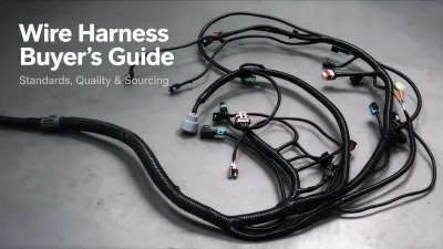
A wire harness is a pre-assembled set of wires, cables, connectors, and terminations that is routed, bundled, and protected as a single engineered unit, then installed into a machine as one part. Bundling many individual circuits into one harness brings three practical benefits: it keeps a complex system installable and serviceable, it protects the conductors against mechanical damage and environmental exposure, and it standardizes how the product is built on a production line.
How a Harness Is Engineered
A harness is not a random collection of wires — it is an engineered unit. Three inputs must be defined before any conductor is chosen, and these inputs are also the starting point for the design process described in the next section:
-
The electrical schematic — the circuits and loads that must be connected, including current per circuit, voltage, signal type, and grounding requirements.
-
The mechanical environment — routing space, temperature extremes, vibration, flexing, fluid and chemical exposure, and ingress protection needs.
-
The interface definitions — the connectors required at every entry and exit point, including mating standards and sealing class.
How Wire Harnesses Are Designed
Harness design is the work of converting a schematic into a drawing a production line can build repeatably. Starting from the three inputs above, each design decision below affects performance, cost, and reliability, so they are made together rather than in isolation.
Selecting Wires
Wire is chosen per circuit from two directions at once. Size (gauge) is set by current carrying capacity and acceptable voltage drop: select a conductor that stays within its ampacity rating at the worst-case temperature, and check that voltage drop across the full length stays inside the load's tolerance — the math is covered in a standard voltage-drop calculation. Insulation is set by the environment: choose a temperature class that clears the worst-case ambient plus self-heating, and a jacket material that resists the oils, solvents, abrasion, or UV it will meet in service. Where corrosion resistance is a concern, tinned copper may be suitable, depending on the environment, terminal system, and applicable material requirements — conductor selection should consider the complete electrical connection, not just the wire material.
Selecting Connectors
Connector selection maps the interface definition to a family: sealed or unsealed, circular or rectangular, board-level or inline. The decisive criteria are current and voltage rating, terminal size and crimp compatibility, sealing class, mating cycle life, and latching or locking that survives the vibration of the application. For applicable automotive crimp applications, specifications such as SAE/USCAR-21 define validation methods and requirements for cable-to-terminal electrical crimps; connector-level performance and environmental requirements must be evaluated against the relevant connector specifications and customer requirements.
Routing and Branch Design
Routing turns the schematic into physical paths: where each wire runs, where branches split off, and how bundles are held in place. This is where the mechanical environment enters the design. Grommets protect wires passing through panels, clamps and straps control position and absorb vibration, and strain relief keeps flexing at connectors away from the termination. Service loops and spare length give the installer working room without creating chafe points.
Specifying Protection
Protection is specified according to exposure, not habit. Abrasion and chafe call for braided sleeving or conduit; heat calls for heat-shrink rated to the temperature class; moisture and chemical exposure call for sealed tape, loom, or a sealed connector system. The right choice balances protection against weight, cost, and routing stiffness — over-specifying protection adds cost and makes the harness harder to route.
Building the Documentation Package
The design is not complete until it is documented. A manufacturable package contains the harness drawing, the pin list or pin-to-pin matrix, and the test specification that production builds and verifies against. For regulated industries this documentation also carries the traceability the end customer will audit.
Designing for Manufacturability
A harness the line can build repeatably beats a theoretically elegant one it cannot. Design for manufacturability means confirming that each crimp uses a validated terminal-and-tool combination, that wire sizes and lengths are within standard machine ranges, that the full-size board layout reflects the drawing, and that drawing dimensions and process specifications define achievable tolerances, inspection methods, and assembly requirements that support repeatable production across trained operators and approved tooling.
How Wire Harnesses Are Manufactured
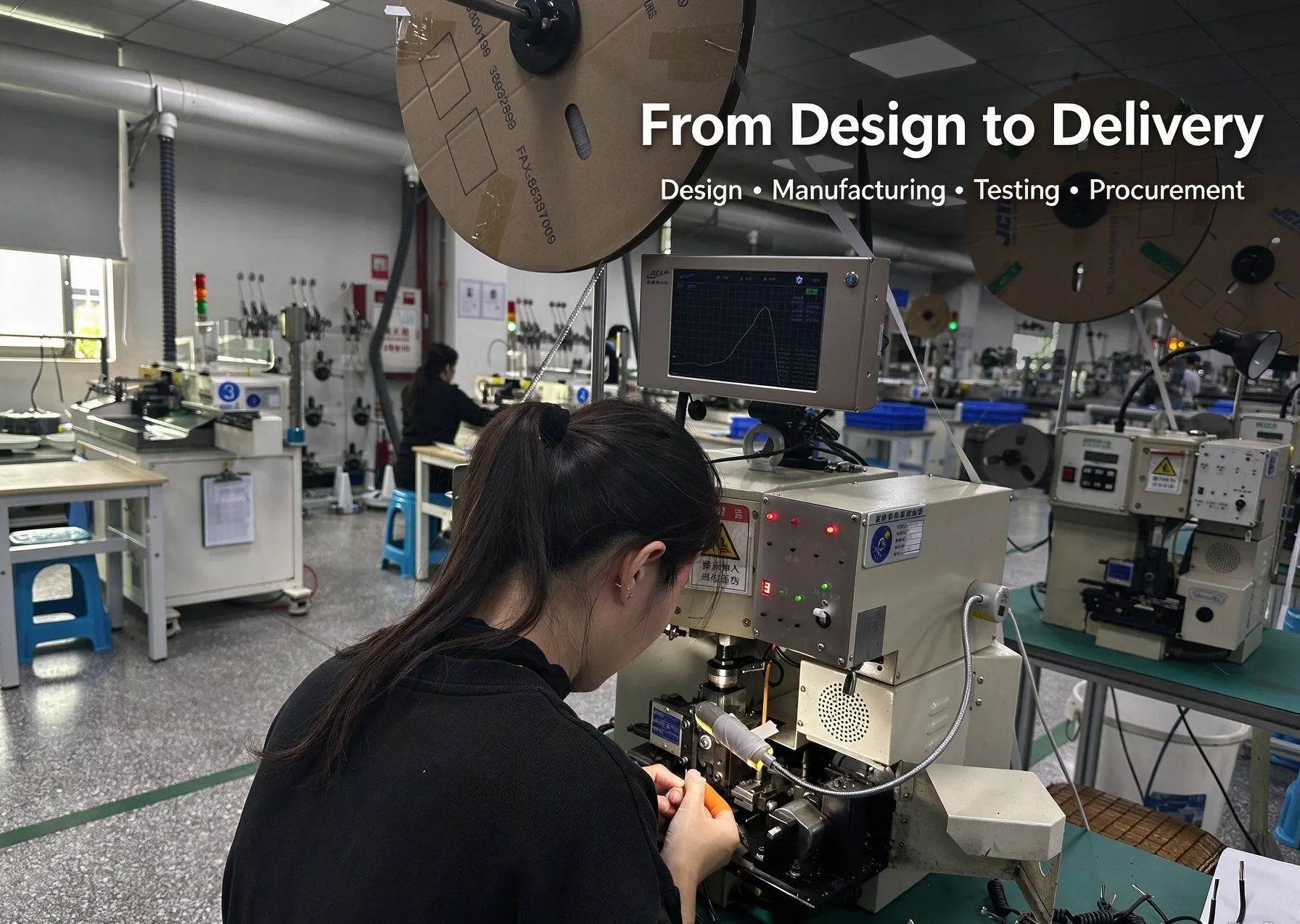
Manufacturing turns the drawing into product through a controlled sequence, and the discipline of that sequence is what makes quality repeatable rather than lucky. Where electrical testing happens in the flow is noted below; how the tests are selected and run is covered in Quality Control and Testing.
The Production Flow
-
Wire is cut and stripped to length, with stripping quality set by the drawing.
-
Terminals are crimped onto each wire end using calibrated tooling — the crimp is the current-carrying joint, and its integrity defines harness reliability.
-
Wires are sub-assembled and terminals inserted into connector housings to the drawing.
-
The bundle is laid out on a full-size board that mirrors the drawing, which fixes routing and branch positions.
-
Bundling and protection are applied: ties, tape, sleeving, conduit, and heat-shrink per specification.
-
The finished harness undergoes electrical testing according to the product specification and control plan. Continuity and short-circuit checks are commonly used to verify circuit connections, while insulation resistance, dielectric withstand, and functional tests are applied when required.
-
Final inspection checks workmanship against the standard, and results are documented for traceability.
The Crimp Joint: Where Reliability Is Won or Lost
Every electrical connection in a harness depends on a mechanically sound crimp. A properly designed and validated crimp creates a stable mechanical and electrical connection between the conductor and terminal; its performance depends on the terminal design, conductor construction, tooling, crimp geometry, and process control. That is why crimping is calibrated and verified rather than left to chance. The verification methods used — crimp height, pull-out force, electrical resistance, and cross-section — are applied as required by the applicable specification and validation plan, and are detailed in Quality Control and Testing.
Materials and Components
The building blocks of a harness are few, but each must be selected to its role.
Wire
Copper is the standard conductor material, tinned where corrosion resistance matters. Insulation is chosen by temperature class and environment. UL Wire Style numbers help identify defined wire constructions and associated ratings — verify the applicable voltage and temperature ratings, conductor construction, insulation materials, and certification details against the wire manufacturer's documentation. Fine-stranded conductors can improve flexibility, but flex life also depends on conductor construction, insulation, bend radius, movement profile, and the cable's rated application; repeatedly flexed harnesses should be designed and validated for the actual motion and installation conditions.
Terminals and Splices
Terminals and splices are selected in crimp families matched to gauge and environment. Common terminal forms include ring, spade, blade, and pin types; splices include ultrasonic welds and crimped butt splices, chosen for strength, compactness, and pull-out resistance. Sealed crimps are used where moisture can enter. Because the crimp is the critical joint, terminal and tooling compatibility is validated as part of design for manufacturability.
Connectors
Connectors are chosen per interface and duty from established families: sealed or unsealed, circular or rectangular, board-level or inline. Sealed connectors keep water and dust out; unsealed types serve interior and protected locations; circular connectors suit rugged field duty; rectangular and board-level types serve dense or internal connections. Sealing class, current and voltage rating, and mating-cycle life are the deciding parameters.
Protection
Braided sleeving, conduit, and heat-shrink each have a role. Heat-shrink seals and strain-relieves terminations and splices; sleeving and conduit guard against abrasion and chemicals; tapes and ties bundle and locate the harness. Protection is specified to the exposure, not to a default, balancing weight, cost, and routing stiffness against the environment it must survive.
Quality Control and Testing
Harness quality rests on two pillars: the integrity of every crimp and the completeness of electrical test coverage. Everything else is documentation that makes the first two auditable.
Crimp Verification
Pull-test sampling confirms that crimps hold within specification. Cross-section analysis can be used to examine crimp geometry and conductor distribution against the applicable terminal, customer, or process-validation criteria, and it is the tool that detects the under-crimps and over-crimps which cause intermittent or premature failure. Verified, calibrated crimping tooling is the first line of defense; sampling and sectioning are the proof.
Electrical Testing
Electrical testing is defined by the product specification and control plan rather than applied uniformly to every product. Continuity and short-circuit checks commonly verify that every circuit is connected to the correct pin, catching opens, shorts, and miswires. Insulation resistance and dielectric withstand (hipot) tests verify insulation integrity when required for power or safety-critical classes, and functional tests are added for signal harnesses. Which tests run on 100% of units versus a sample — and which apply at all — depends on the product design, ratings, customer specification, and applicable safety requirements.
Environmental and Sealed Testing
Sealed harness classes add leak testing to confirm the sealing system keeps moisture out. Depending on the duty profile, verification may also include temperature cycling, vibration, and chemical-resistance checks that simulate the real environment — and the sealing class dictates which of these apply.
Documentation and Traceability
For regulated industries, documentation closes the loop: test records, material and lot traceability, and workmanship evidence tie every delivered harness back to its build and verification. This is what makes a quality system auditable rather than merely claimed.
Wire Harness Applications by Industry
Every industry shares the same fundamentals but sets different standards and duty profiles. The standards listed below are examples, not universal requirements for every wire harness used in that industry — applicability depends on the product, installation, target market, customer specifications, and regulatory requirements. The map below shows where the emphasis falls.
|
Application Class
|
What It Demands
|
Examples of Applicable Standards and Specifications
|
|---|---|---|
|
Automotive & Vehicles
|
High volume, vibration, temperature extremes, sealed connectors
|
SAE/USCAR-21 (cable-to-terminal crimps), IPC/WHMA-A-620 (workmanship)
|
|
Industrial & Automation
|
Flex life, oil and coolant exposure, harsh floor environments
|
NFPA 79, IEC 60204-1 (machine electrical systems; harness-specific requirements per design and project spec)
|
|
Medical Devices
|
Tight tolerances, cleanliness, biocompatibility, full traceability
|
IEC 60601-1 (applicability depends on device type and system design)
|
|
Energy & Solar
|
Outdoor UV and weathering, high-current DC
|
UL 4703 (photovoltaic wire; verify current edition), UL 6703 (photovoltaic connectors)
|
|
Aerospace & Defense
|
Precision, low weight, extreme reliability, deep documentation
|
AS50881 (wiring design and installation practice; confirm applicable revision and project spec), IPC/WHMA-A-620
|
|
Telecom & Computing
|
Signal integrity, high density, controlled impedance
|
Applicable TIA standards, IPC/WHMA-A-620
|
Buying Wire Harnesses: A Practical Checklist
Buying a harness well is mostly about giving the supplier enough information and defining how you will judge the result. Four things decide whether the program goes smoothly or stalls.
Provide Complete Engineering Data
Send the bidders everything they need to quote accurately: the schematic, the harness drawing, the mechanical environment, and the application's duty profile. Incomplete data produces inaccurate quotes and late surprises — a harness quoted on partial information cannot be priced or built correctly.
Qualify Before You Commit
Qualify the supplier on samples, first articles, and capability evidence before scaling up. Samples prove the design and process; first-article inspection proves the production line can hold the specification; capability evidence — training, tooling calibration, test equipment — proves it will keep doing so.
Put Test and Documentation Requirements in the Contract
State the testing and documentation requirements in the contract, not as an afterthought. Define which electrical tests run 100% versus sampled, which workmanship standard applies, and what traceability records must ship with each order. What is not in the contract is what you are least likely to receive.
Assess the Supplier's Process Evidence
Match the supplier's process evidence to the application's criticality. Calibration records, crimp verification, traceability, and test records should be inspectable — for a safety-critical program they are the proof the quality system is real, not just a claim on a brochure.
Getting Started With Your Wire Harness Project
Whether your project is a single prototype or high-volume production, the fastest path to a good result is the same: bring the schematic, the mechanical environment, and the interface definitions, and let an experienced manufacturer work the design and process with you. Share your project requirements through the contact page and the engineering team will respond with the practical route to a reliable, buildable harness.