In electrical engineering and wire harness design,ampacity rating defines the maximum continuous current a conductor can safely carry under specified installation and thermal conditions, without exceeding insulation temperature limits or incurring permanent thermal damage. Often misunderstood as a fixed wire property, ampacity is a dynamic, condition-dependent value. Accurate interpretation of industry standard tables and rigorous consideration of real-world derating factors are critical to preventing overheating, insulation degradation, and electrical fire risks—especially for custom cable assemblies, building wiring, and industrial harness systems.
1. Core Principle of Ampacity Ratings
Ampacity is governed by steady-state thermal equilibrium. As electric current flows through a conductor, electrical resistance generates heat according to the relationship (P = I^2R). Safe continuous operation requires this heat to dissipate into the surrounding environment without causing the conductor or its insulation to exceed its applicable temperature limits.
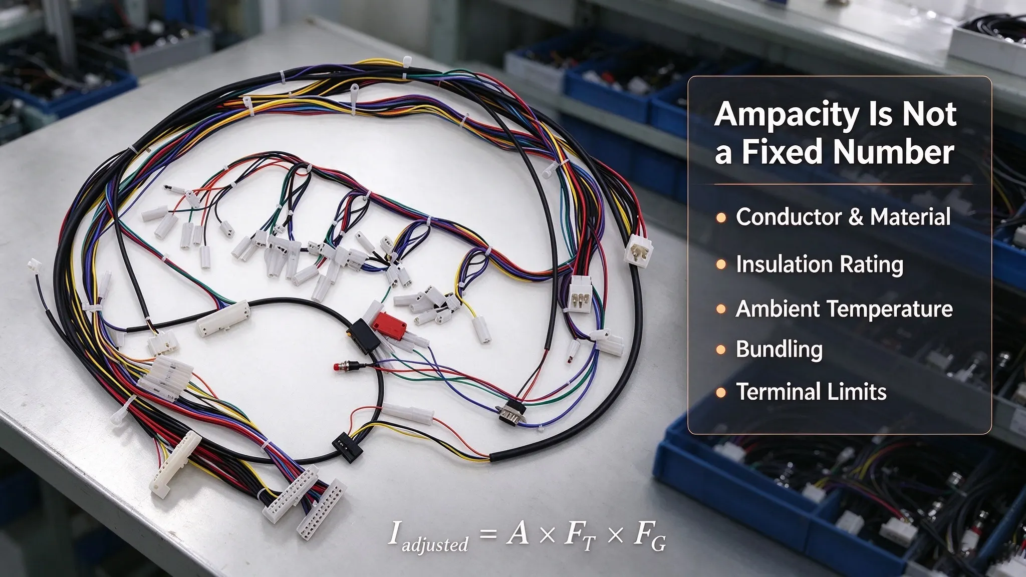
Common conductor insulation temperature ratings in building-wiring applications include 60°C, 75°C, and 90°C, although ratings vary by product and applicable standard. Sustained operation above the permitted temperature can accelerate insulation aging and may cause cracking, melting, or electrical failure. Unlike conductor material or wire gauge, ampacity is not a fixed value for every installation; it depends on ambient temperature, conductor arrangement, heat dissipation, insulation rating, and applicable installation requirements.
2. Standard Ampacity Reference Frameworks: NEC vs. IEC
Ampacity references include NEC Table 310.16 and the IEC 60287 series, but these serve completely different purposes and cannot be used interchangeably. NEC Table 310.16 provides standardized allowable ampacity values for specified building conductors under fixed installation and environmental conditions, serving as a direct lookup table for conventional architectural wiring. In contrast, the IEC 60287 series is a set of computational standards that define systematic methods for calculating cable current ratings, covering conductor power losses, permissible temperature rise, cable structural parameters, and complex external thermal environmental conditions, rather than offering fixed universal ampacity figures.
NEC Table 310.16 provides allowable ampacity values for conductors under the installation conditions specified by the table and applicable code provisions. Its reference conditions include an ambient temperature of 30°C and no more than three current-carrying conductors in the relevant raceway, cable, or earth installation. These baseline conditions do not eliminate the need to apply other relevant code requirements, including ambient-temperature corrections, conductor-count adjustment factors, and terminal temperature limitations that govern final allowable ampacity.
2.1 Key Baseline Parameters in Standard Ratings
Wire gauge (AWG) is the most intuitive factor affecting baseline ampacity: in standard AWG sizing rules, a smaller gauge number corresponds to a larger conductor cross-sectional area and lower electrical resistance. Conductor material also impacts electrical performance. Copper generally has lower electrical resistivity than aluminum of the same cross-sectional area. However, the allowable ampacity of either conductor depends on its construction, insulation temperature rating, installation conditions, and applicable code requirements, rather than conductor material and size alone. Insulation temperature rating defines the maximum safe operating temperature of a cable system, serving as a core upper limit for current-carrying capacity in all installation scenarios.
2.2 NEC 2020 Table 310.16 Baseline Ampacity Values
The table below illustrates code-based baseline ampacity values for common copper conductors, referenced from NEC 2020 Table 310.16. All values apply only to specified baseline conditions and are not universal ratings for all wiring scenarios:
Disclaimer: Values are NEC 2020 code-based reference ratings under standard baseline conditions. Data is for technical reference only and cannot be directly applied to all wiring systems. Final ampacity selection must account for code-specified correction/adjustment factors, terminal temperature ratings, and equipment-specific requirements. This table is intended for conventional building wiring and is not valid for automotive wire harnesses, internal equipment wiring, or tightly bundled custom cable assemblies.
|
Wire Gauge (AWG)
|
60°C Insulation (A)
|
75°C Insulation (A)
|
90°C Insulation (A)
|
|
14
|
15
|
20
|
25
|
|
12
|
20
|
25
|
30
|
|
8
|
40
|
50
|
55
|
|
6
|
55
|
65
|
75
|
|
4
|
70
|
85
|
95
|
These values are code-based reference ratings under specified conditions, not universal ampacity limits for every application. Actual conductor selection must account for applicable correction and adjustment factors, terminal temperature ratings, and equipment-specific requirements to ensure safe and compliant operation.
3. Critical Real-World Factors That Derate Ampacity
Standard table values represent ideal baseline performance. In field installations, multiple environmental and mechanical factors disrupt thermal balance, reduce effective heat dissipation, and lower real-world ampacity. Reliable harness design requires adjusting baseline values for site-specific conditions.
3.1 Ambient Temperature Conditions
Standard ampacity tables are calibrated for a 30°C ambient temperature. Elevated ambient temperatures reduce the thermal gradient between the conductor and surrounding air, slowing heat dissipation and requiring mandatory ampacity derating. Common high-risk environments include outdoor sun-exposed routing, boiler rooms, sealed control cabinets, and high-temperature industrial enclosures.
Lower ambient temperatures may improve heat dissipation and increase calculated ampacity under some conditions. Any increase must follow the applicable correction factors and conductor, insulation, terminal, and equipment limitations rather than being assumed from ambient temperature alone.
3.2 Conductor Bundling and Group Installation
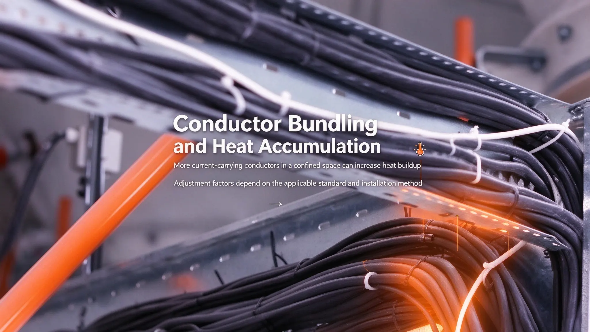
When multiple current-carrying conductors share a raceway, cable, or other confined installation space, their combined heat generation creates localized thermal accumulation, which reduces the allowable ampacity of each individual conductor. Under applicable NEC rules, adjustment factors generally apply when the number of current-carrying conductors exceeds three under specified installation conditions, rather than triggering a universal derating for three or more conductors in all scenarios.
Other regional standards and specialized cable installation methods may adopt distinct grouping and derating rules. As such, designers must verify applicable industry requirements before selecting and applying conductor grouping derating factors, and distinguish between total wire count and code-defined current-carrying conductor count in custom harness designs.
3.3 Installation Method and Thermal Environment
Installation method strongly influences heat dissipation and allowable ampacity. Conductors installed in free air, raceways, cable trays, or underground systems feature distinct thermal environments, resulting in different current rating limits. Notably, free-air installation does not guarantee higher ampacity in all cases, as actual performance depends on conductor spacing, arrangement, ambient radiation conditions, and applicable code specifications—NEC provides dedicated standalone tables for free-air wiring scenarios.
For buried cables, soil thermal resistivity, moisture conditions, burial depth, and cable spacing also jointly affect heat transfer efficiency and steady-state current-carrying capacity. All installation-specific ampacity values must be determined using corresponding standard tables or authoritative calculation methods.
3.4 Continuous Loading and Material Degradation
Ampacity ratings defined by NEC lookup tables and IEC 60287 calculations are based on steady-state thermal equilibrium and continuous constant-current operating conditions, not intermittent load test data. The core principle of valid ampacity rating is maintaining stable thermal balance: sustained resistive heating from continuous current flow must stay within the maximum temperature limits of conductors and insulation materials.
Long-term circuit reliability is compromised by repeated thermal cycling, prolonged excessive operating temperatures, mechanical insulation damage, conductor corrosion, and loose electrical connections—rather than generic insulation aging. Damaged insulation loses its thermal resistance and protective properties, increasing the risk of electrical breakdown. Degraded or poor electrical connections create localized high resistance points, leading to concentrated overheating even at standard rated current levels. These defects require targeted inspection and maintenance, and cannot be mitigated by arbitrary, generalized ampacity derating adjustments.
4. Practical Ampacity Adjustment for Engineering Design
The core of compliant ampacity design is conditional correction and multi-layer verification, rather than direct table lookup. Standard baseline values serve only as a starting point for field application.
The core of reasonable ampacity application follows a standardized correction logic, with critical preconditions and limitations. Where the applicable code permits this approach, a preliminary adjusted ampacity can be calculated by multiplying the table baseline value by the relevant ambient-temperature correction factor and conductor-count adjustment factor. This two-step correction serves only as a preliminary calculation reference, not a final valid rating.
The preliminary calculated value must be further verified against terminal temperature ratings, conductor insulation limits, equipment manufacturer specifications, and other mandatory code requirements. Notably, conventional building wiring ampacity tables are not universally applicable. For custom wire harnesses, automotive cables, and internal equipment wiring, designers must adopt wire manufacturer-specific ratings and industry-specific product standards instead of directly applying building wiring rules.
4.1 Ampacity Derating Calculation Formula
Professional ampacity adjustment follows standardized code-based logic. The formula below defines the industry-standard method for calculating preliminary derated ampacity, compliant with NEC rules and consistent with the steady-state thermal calculation principles specified in the IEC 60287-1-1:2023 standard (Electric cables – Calculation of the current rating – Part 1-1: Current rating equations and calculation of losses).
The preliminary adjusted ampacity formula is:
$$I_{\text{adjusted}}=A\times F_T\times F_G$$
Where: - $$A$$ = Baseline ampacity value from standard tables under ideal test conditions - $$F_T$$ = Ambient temperature correction factor (code-specified based on actual operating temperature) - $$F_G$$ = Conductor grouping adjustment factor (determined by the number of current-carrying conductors and installation mode)
Application Note: All correction factors must be sourced from the latest applicable industry codes or official cable manufacturer technical data. The calculated $$I_{\text{adjusted}}$$ value represents only a preliminary derated ampacity, not a final allowable current rating. Final conductor selection must pass cross-verification with terminal temperature limits, insulation thermal ratings, and equipment safety specifications to eliminate overheating risks and ensure full compliance.
4.2 Special Design Rules for Custom Wire Harnesses
A critical industry distinction must be emphasized for B2B harness engineering and procurement scenarios. NEC Table 310.16 data is exclusively calibrated for open/ducted building wiring with limited conductor bundling. It cannot be directly applied to tightly packed multi-core custom harnesses, vehicle wiring systems, and compact internal equipment wiring.
Custom harness environments feature dense conductor bundling, minimal air gaps, confined heat dissipation, and unique terminal and enclosure constraints. These scenarios require manufacturer-certified ampacity ratings, product-specific thermal testing data, and stricter derating schemes than generic building wiring standards. Reliable harness design prioritizes application-specific certification over generalized table values.
5. Conclusion
Ampacity rating is a dynamic, condition-dependent safety parameter rather than a fixed inherent wire specification. Standardized references including NEC Table 310.16 and the IEC 60287 series provide complementary but distinct technical support for cable current rating evaluation: NEC offers intuitive baseline lookup values for conventional building wiring, while IEC 60287 provides rigorous computational frameworks for complex thermal scenarios. Real-world ambient temperature, conductor grouping density, installation heat dissipation conditions, and long-term operating loads collectively determine the actual safe current-carrying capacity of cables and harnesses.
Accurate ampacity evaluation relies on three core steps: referencing compliant baseline data, applying scenario-specific correction and adjustment factors, and verifying against terminal, insulation and equipment limitations. Generic table values and one-size-fits-all derating rules are insufficient for custom wire harness, automotive, and industrial equipment wiring applications. Mastering these standardized technical rules and real-world correction methods eliminates subjective design errors, reduces electrical safety hazards, ensures full code compliance, and extends the service life of electrical and harness systems. For professional B2B engineering and procurement, rigorous ampacity assessment is an essential foundation for reliable, cost-effective wiring system design.
Reference Sources
1. NFPA NEC 2020, Table 310.16 – Allowable ampacities of insulated conductors rated 0 through 2000 volts. 2. IEC 60287-1-1:2023, Electric cables – Calculation of the current rating – Part 1-1: Current rating equations (100 % load factor) and calculation of losses. Official publication:
https://webstore.iec.ch/en/publication/68118