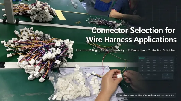
Connector selection affects the electrical performance, mechanical reliability, environmental protection, and manufacturability of a wire harness. An unsuitable connector can cause overheating, intermittent contact, water ingress, or assembly defects. This technical guide consolidates practical, manufacturing-focused criteria for wire harness connector selection, covering critical electrical and mechanical rules, environment-based IP rating standards, mainstream connector application boundaries, standardized selection workflows, and mass production validation requirements to help engineers avoid common field failures.
1. Key Factors in Wire Harness Connector Selection
Professional connector selection rejects generalized series-based parameter matching. All performance specifications must be verified against specific part number datasheets, with full consideration of derating conditions, assembly configuration, and production compatibility. The core evaluation dimensions are summarized below.
1.1 Electrical Performance and Derating Rules
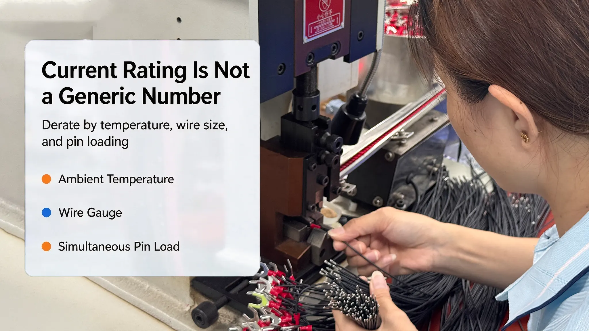
Rated current and voltage values cannot be universally applied to an entire connector series. Actual current-carrying capacity is determined by contact size, matched AWG wire gauge, ambient temperature, simultaneous multi-pin loading, and allowable temperature rise.
Practical electrical verification covers four core items. Continuous and peak current ratings require thermal derating for high-temperature working environments to prevent overheating. Dielectric withstand voltage must exceed system operating voltage to avoid insulation breakdown. Stable low contact resistance minimizes long-term operational heat generation. For high-speed and high-frequency circuits, connector impedance and transmission-line characteristics must align with interface design requirements; proper impedance control reduces signal reflections and preserves signal integrity.
1.2 Mechanical Performance and Structural Reliability
Mechanical reliability focuses on application-specific durability rather than universal lifecycle claims. Mating cycle tolerance varies drastically by sub-model and test conditions; portable consumer devices require high-cycle connectors, while industrial and automotive fixed harnesses prioritize vibration resistance.
Two key anti-loosening structures ensure long-term connection stability. Secondary locking mechanisms secure terminals inside the housing to prevent terminal back-out, while Connector Position Assurance (CPA) devices confirm full mating and eliminate incomplete connections under sustained vibration and torsion. All selections must reserve sufficient installation space and routing stress relief to avoid assembly interference and wire fatigue damage.
1.3 Environmental Protection and Standardized IP Ratings
Operating temperature ranges are part-number dependent, with no universal standard for automotive or industrial series. Engineers must confirm temperature limits from official datasheets and apply current derating for extreme high-temperature environments.
IP protection ratings follow strict standardized test conditions and cannot be bound to specific industries or connector series. IEC 60529 defines general enclosure IP codes, while ISO 20653:2023 specifies road vehicle IP requirements, including high-pressure cleaning rules for “K” suffix ratings. IP54 provides basic splash and dust protection for sheltered indoor environments. IP6X delivers full dust-tight performance, and IPX7 offers temporary immersion protection for fully mated assemblies. IP69K applies exclusively to high-pressure, high-temperature spray washing scenarios typical of automotive chassis and industrial cleaning processes. IP terminology must strictly match certified standards to avoid confusing IP69, IP69K, and IPX9K specifications. For corrosive marine and chemical environments, selection depends on media characteristics, contact plating, and housing material chemical resistance rather than generic material assumptions.
1.4 Wire, Terminal and Tooling Compatibility
Full system matching of terminals, wires, sealing accessories, and calibrated crimp tooling is mandatory for qualified harness assemblies. Mismatched terminal part numbers, conductor cross-sectional areas, or cable insulation outer diameters directly cause unqualified crimping, virtual connection, and wire detachment. Custom seals and cavity plugs must precisely fit cable outer diameters to guarantee harness tightness and long-term stability.
2. Connector Types and Practical Application Boundaries
Connector selection is requirement-driven instead of brand or series stereotyped. Different sub-models within one series have distinct performance limits; all application parameters require part-level datasheet verification.
Consumer and commercial electronics: Molex Micro-Fit 3.0 and JST series are widely used for compact low-power power and signal harnesses in consumer appliances and smart devices. Current ratings vary significantly by part number, wire gauge, temperature, and pin loading. No universal series current value applies, and all working parameters require targeted datasheet confirmation.
Automotive and heavy-duty equipment: TE Connectivity automotive series and DEUTSCH DT connectors support harsh vehicle and industrial environments. TE automotive connectors cover multiple sub-series with differentiated wire gauge adaptation ranges. Standard DEUTSCH DT Size 16 contacts deliver a verified 13A continuous current under standardized test conditions and matched wire specifications. The IP rating of DT assemblies depends on mating components, seals, plugs, and installation conditions, with no series-wide universal waterproof performance.
Aerospace systems: Amphenol ARINC 600 series serves aviation interconnection applications. Impedance characteristics, bus compatibility, and environmental grades are fully customized by part number. Engineers must verify shielding structure, contact layout, and aviation-specific specifications for individual component selections.
3. Common Selection Mistakes and Standard Five-Step Workflow
Most harness field failures stem from improper specification matching and incomplete verification. The two most prevalent errors are under-specification (insufficient current, temperature, or IP grade causing field failure) and over-specification (blind adoption of high-grade connectors leading to unnecessary cost inflation).
The standardized five-step selection workflow eliminates subjective judgment and ensures engineering accuracy:
1. Confirm core working conditions including voltage, continuous/peak current, ambient temperature, vibration, and exposure risks.
2. Match AWG wire size, conductor cross-section, and insulation dimensions to lock compatible terminal specifications.
3. Screen qualified connectors based on verified electrical derating and environmental certification parameters.
4. Validate assembly feasibility including installation space, locking structure, tool adaptation, and stress relief routing.
5. Conduct application-targeted sample testing per project risk level and customer specifications before mass production.
4. Manufacturing and Mass Production Validation
Distinct from theoretical design selection, factory-level connector evaluation focuses on crimping consistency and batch production stability, with two core verified dimensions.
4.1 Crimping System and Mechanical Verification
Two independent mechanical tests prevent different failure modes. Crimp pull-force testing verifies wire-to-terminal crimp joint strength to avoid wire detachment. Terminal retention testing confirms terminals are securely locked in housings to prevent back-out under vibration. All crimp height and tensile criteria must comply with manufacturer specifications and calibrated tooling requirements.
4.2 Production Release Validation Rules
Mass production verification follows approved product specifications and quality control plans. Test items, sampling frequency, and acceptance criteria are customized based on application risk and customer requirements, including continuity testing, insulation resistance testing, crimp quality inspection, and sealing validation. Not all test items apply to every harness project.
5. Practical Wire Harness Connector Selection Checklist
This actionable checklist supports one-stop parameter verification for engineering design and production review.
|
Verification Dimension
|
Key Confirmation Parameters
|
|
Electrical Requirements
|
Working voltage, continuous/peak current, temperature rise derating, high-speed signal impedance control
|
|
Wire & Terminal Matching
|
AWG wire gauge, conductor cross-section, insulation outer diameter, compatible terminal part number
|
|
Structural & Mechanical Design
|
Pin count, mating compatibility, anti-vibration structure, secondary lock & CPA configuration
|
|
Environmental Adaptability
|
Part-specific temperature rating, standardized IP grade, corrosion and cleaning environment adaptability
|
|
Production & Verification
|
Specified crimp tooling, crimp pull-force & terminal retention requirements, customized pre-production testing
|
6. Conclusion
Reliable wire harness connector selection is a datasheet-driven, manufacturing-oriented engineering process. The core principles include avoiding generalized series parameter assumptions, applying temperature and load derating rules, ensuring full compatibility of terminals, wires, seals and tooling, and completing customized pre-production verification. Strict implementation of standardized selection workflows and factory validation rules effectively eliminates design and manufacturing defects, ensuring long-term system stability and batch consistency for wire harness assemblies.
References
1. Molex Micro-Fit 3.0 Official Product & Datasheet Resources:
2. TE DEUTSCH DT Series Official Technical Specification:
3. IEC 60529:1989 Standard (IP Protection Codes for Electrical Enclosures):
4. ISO 20653:2023 Standard (Road Vehicle IP Protection Requirements):
FAQs About Wire Harness Connector Selection
The following FAQs resolve core practical challenges in connector specification and production validation.
1. Why can’t I use series-level rated current values for harness design?
Series current parameters are only general references, not universal design standards. Actual current capacity depends on specific contact size, matched wire gauge, ambient temperature, simultaneous multi-pin loading, and temperature rise derating. Each connector series contains multiple sub-models with distinct electrical limits. All current ratings must be confirmed via official manufacturer datasheets for the exact part number and working configuration to avoid overheating and contact failure.
2. How do I select the correct IP rating for wire harness connectors?
IP rating selection depends on actual exposure conditions and certified standard test requirements, not application industry or connector series. IP54 suits sheltered environments with limited dust and water splashes. IP67 is required for applications exposed to temporary water immersion. IP69K is exclusively for equipment requiring high-pressure, high-temperature cleaning, complying with ISO 20653 vehicle-specific standards. Engineers must verify full assembly conditions including mating status, seal configuration, and official test specifications before confirming IP grades.
3. What are the main causes of mass-production crimp failures?
Most crimp defects stem from mismatched system components rather than single operational errors. Common causes include incompatible terminal and wire specifications, incorrect crimp height or uncalibrated tooling settings, and mismatched cable insulation diameters and sealing accessories. Reliable connector selection requires full compatibility verification of terminals, conductors, seals, and dedicated crimp tooling before mass production.
4. How to prevent connector selection errors before mass production?
Error prevention relies on standardized design workflows and customized factory validation. Engineers must verify all electrical, mechanical, and environmental parameters based on specific part datasheets instead of generalized series attributes. During pre-production, complete targeted sample testing including crimp mechanical verification, sealing validation, and electrical performance testing. All test criteria and sampling plans should be defined according to project risk level and customer specifications to eliminate under-specification, over-specification, and assembly compatibility issues.