Table of Contents
- 1. What is an FPC connector?
- 2. Common structural types of FPC connectors
- 3. Key Parameters and Selection Considerations for FPC Connectors
- 4. The difference between FPC and FFC
- 5. Common application scenarios of FPC connectors
- 6. Reliability Engineering of FPC Connectors
- 7. Engineering Selection Recommendations for FPC Connectors
- 8. WIRE HARNESS ASSEMBLY Solution
- 9. FAQ
By quanyu lee
2025-12-08 14:14:41
FPC Connector Guide: Construction, Selection, Reliability, and Engineering Practice
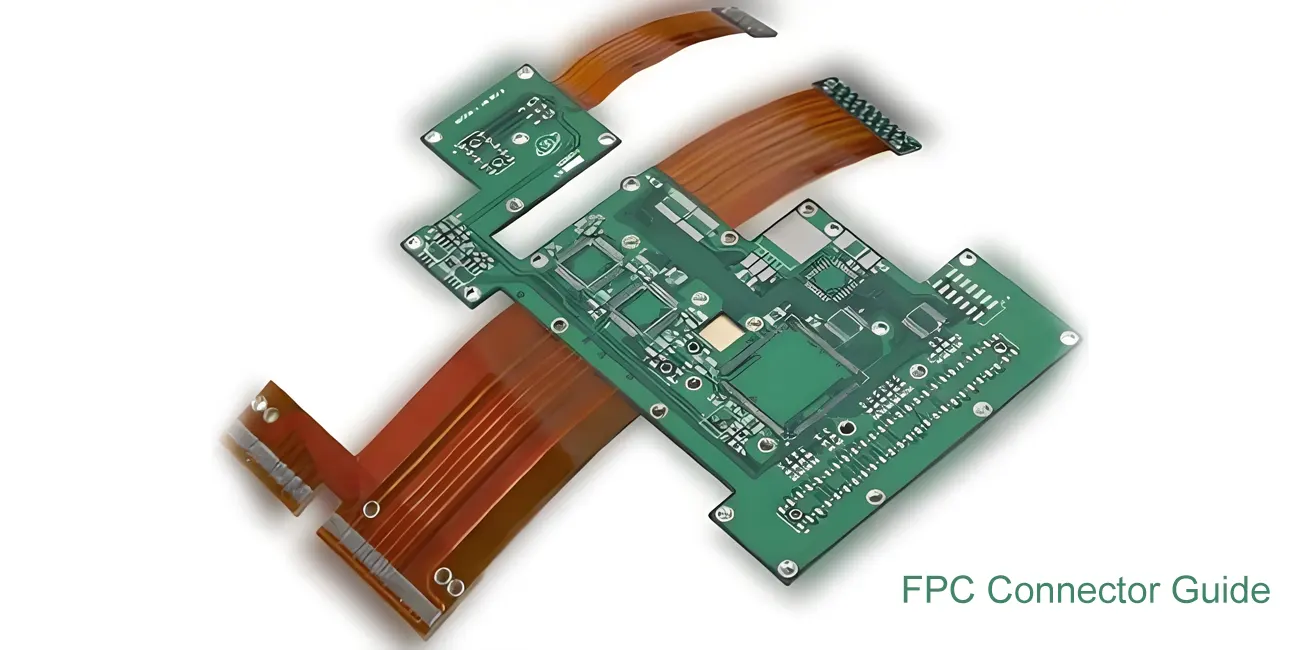
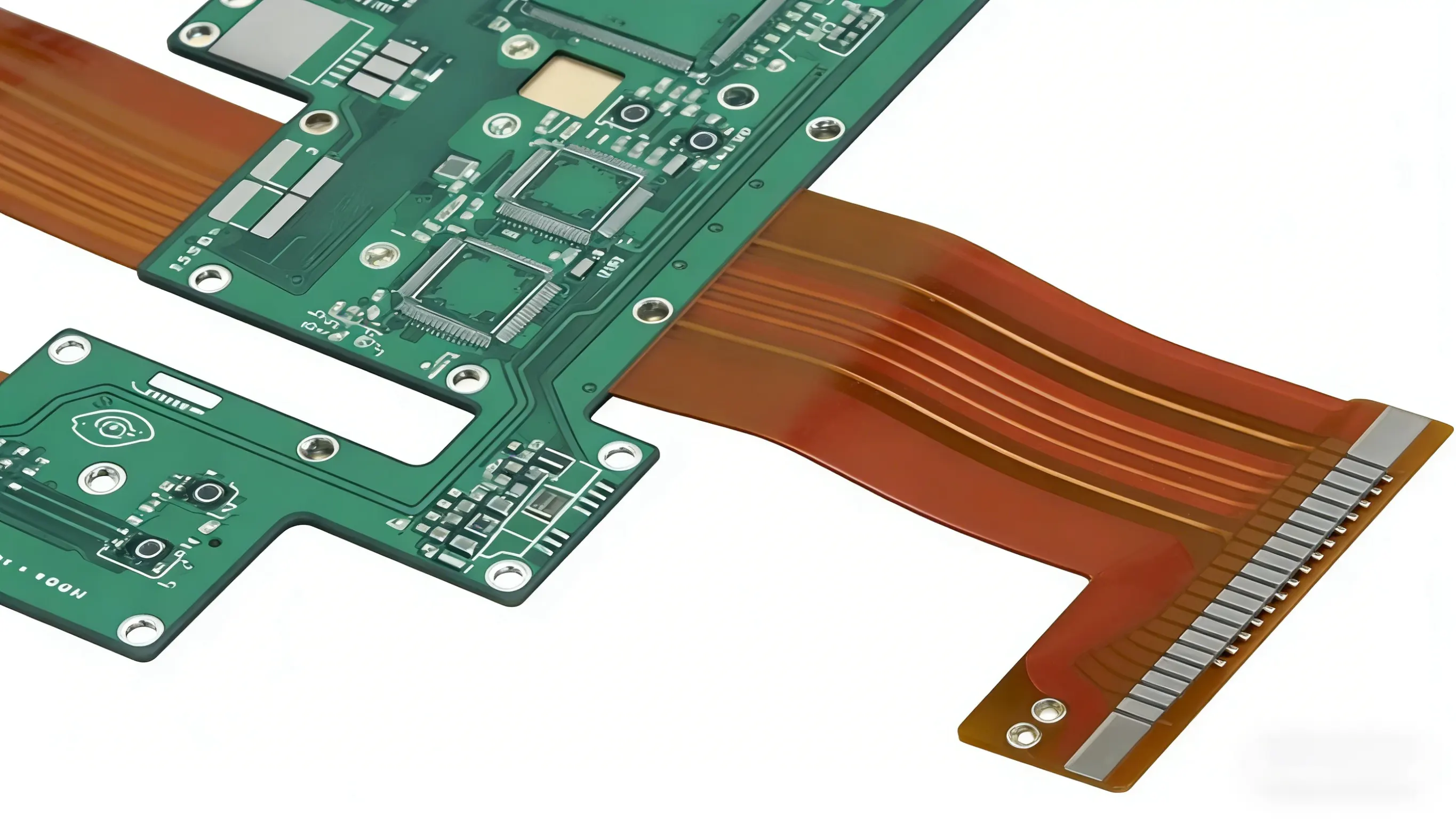
Flexible Printed Circuit (FPC) connectors are among the most critical high-density connectivity solutions in modern electronic products. Whether in smartphones, laptops, medical devices, automotive electronics, or industrial control systems, FPC connectors play a vital role in achieving high-density, high-reliability signal transmission within limited space.
As devices become increasingly thin, more flexible, and more modular, the design, selection, and reliability requirements for FPC connectors are more stringent than ever.
1. What is an FPC connector?
An FPC (Flexible Printed Circuit) connector is a specialised connector that connects flexible printed circuit boards (FPCs) to the main PCB. It achieves a detachable connection of signals and power through crimping, snap-fit, or ZIF clamping. It is widely used in:
- Display modules for smartphones, tablets, and laptops
- Automotive centre console screens, cameras, and ADAS modules
- Medical testing instruments and wearable devices
- Industrial automation, instrumentation, and sensor systems
The core value of FPC connectors lies in their thinness, high density, flexibility, and modular design.

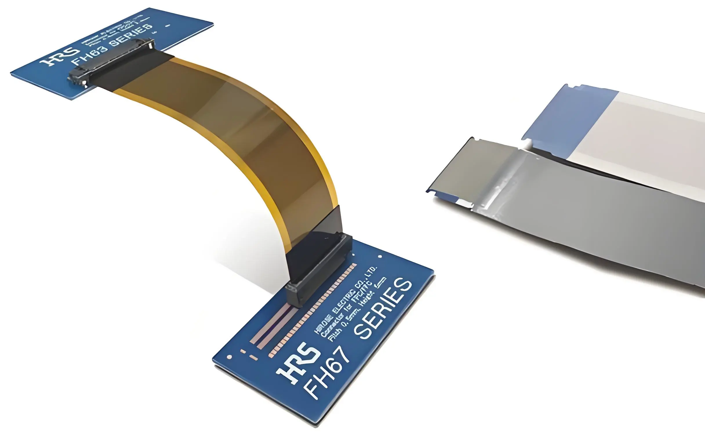
2. Common structural types of FPC connectors
① ZIF (Zero Insertion Force) connector
- FPC can be inserted without force.
- Features a snap-on locking mechanism, suitable for high-density applications.
- Commonly used in displays, keyboard modules, and camera modules.
② LIF (Low Insertion Force) Connector
- The insertion and extraction forces are slightly greater than ZIF, but the structure is simpler.
- The cost is lower.
- Suitable for low to medium density applications, such as small control boards.
③ Flip-lock connector
- Features a flip-lock mechanism that locks in place after insertion.
- More stable than ZIF connectors.
④ Front/Rear Insertion FPC Connector
- Optimised structure based on insertion direction
- Suitable for space-constrained equipment interiors
⑤ Top/Bottom Contact
- Top Contact: FPC gold fingers facing upwards
- Bottom Contact: Used for small-sized modules with limited structural space.
3. Key Parameters and Selection Considerations for FPC Connectors
Incorrect selection in engineering often leads to module scrapping or complete rework. The following are the most critical parameters:
① Pin Count
- Commonly, 4–80 pins; some high-end displays can reach 120 pins.
② Pitch
Common specifications:
- 1.00 mm
- 0.50 mm
- 0.30 mm
- 0.20 mm (for ultra-thin devices)
A smaller pitch results in higher signal density but reduces durability and requires higher assembly precision.
③ Mating/Removal Durability
- Typical range: 20-100 cycles.
- High-end ZIF can reach 200 cycles.
④ Current and Signal Capabilities
- Control Signals: Generally supports 0.2–0.5 A per pin
- LCD Signals: Requires shielded FPC in EMI environments
- High-Speed Signals: Requires support for LVDS / MIPI / eDP
⑤ Structural Height
- Ultra-thin type: 0.6–1.0 mm
- Standard type: 1.0–2.5 mm
⑥ Locking Structure Strength
- Determines vibration resistance, especially critical for automotive electronics.
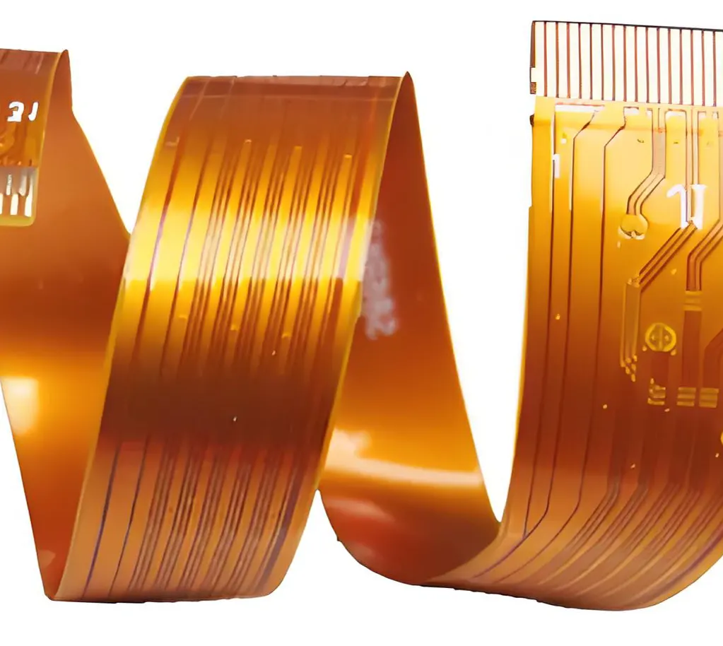
4. The difference between FPC and FFC
| project | FPC | FFC |
| composition | PI + copper foil lamination into a flexible PCB | Parallel copper wire + PET |
| form | Circuit design is possible, drilling is possible, and multi-layer operation is possible. | Pure parallel cable |
| cost | Middle to high | Low |
| signaling capability | Supports high speed and high density | Medium speed, low cost |
| application | Display/Camera/Inter-module Communication | Printers, home appliances, scanners |
5. Common application scenarios of FPC connectors
- Mobile Phone LCD/OLED Display Modules
- Camera Modules / ToF / LiDAR
- Tablet & Laptop Keyboards
- Medical Probes, Ultrasonic Equipment
- Industrial HMIs, PLCs
- Automotive Instrument Panels, Central Control Screens, Sensor Systems
In these devices, the FPC connector must withstand:
- Micro-vibration and continuous bending
- Temperature cycling (-40°C to +85°C)
- EMI interference
- Compact assembly space
- Multi-layer FPC distributed management
6. Reliability Engineering of FPC Connectors
An excellent FPC design must simultaneously satisfy:
1. Mechanical Reliability
- The latches must withstand insertion and extraction pressure.
- The FPC must not be bent below the minimum bending radius.
- Prevent the FPC from being pulled off due to vibration.
2. Electrical Stability
- Impedance control is required for high-frequency circuits.
- Contact points must meet plating thickness specifications (e.g., gold plating ≥ 0.2 μm).
3. Environmental Resistance
- Moisture-proof, dust-proof, and corrosion-proof
- Automotive-grade connectors must meet AEC-Q200 specifications.
4. EMC / EMI
- High-speed signals (such as MIPI, LVDS) require ground shielding.
- Avoid placing the signal near high-noise areas during layout.
7. Engineering Selection Recommendations for FPC Connectors
| Application requirements | Recommended choice |
| High-density / ultra-thin devices | 0.3mm pitch ZIF |
| Display module | Following ZIF + shielded FPC |
| Camera module | Flip-lock + EMI structure |
| High-vibration scenarios (automobiles) | Automotive-grade FPC connector with metal locking mechanism |
| cost sensitive | LIF or FFC alternatives |
| High-frequency and high-speed signal | Enhanced ZIF with ground pin |
8. WIRE HARNESS ASSEMBLY Solution
As a professional wire harness customisation factory, WIRE HARNESS ASSEMBLY has long provided products for consumer electronics, automotive, medical, and industrial equipment.
- FPC + FPC Connector Assembly
- Customised FPC/FC Cable Harnesses
- Ultra-thin Flexible Cable Assemblies
- High-speed MIPI/LVDS Shielded Cable Harnesses
- SMT + THT Connector Soldering Service
Their engineering team can perform DFM optimisation based on requirements such as space, signal rate, bending life, and insertion/removal life, and supports small batch and mass production.
9. FAQ
Q1: Is a smaller FPC connector pitch always better?
Not necessarily. A smaller pitch increases assembly difficulty, cost, and reliability. The choice should be based on a combination of pin count and available space.
Q2: What precautions should be taken when using FPCs for high-speed signals?
Shielding structures and ground spacing are required. Double-sided or triple-layer FPCs may be necessary to control impedance.
Q3: What is the importance of the gold finger thickness at FPC contacts?
A thin gold plating can easily lead to poor contact. The standard thickness is recommended to be ≥ 0.2 μm (≥ 0.5 μm for some high-end applications).
Q4: What are the additional requirements for FPC connectors in the automotive industry?
They need to meet AEC-Q specifications, have a high vibration resistance design, a metal locking mechanism, and a heat resistance of 105°C or higher.
Q5: What is the difference between FPC and Flexible Cable Assembly?
FPC belongs to "Flexible PCB", while flexible cable assembly refers to a broader range of cable components, such as FFC, ribbon cables, and flexible coaxial cables.


